Design for manufacturing
Get the part right before the steel is cut
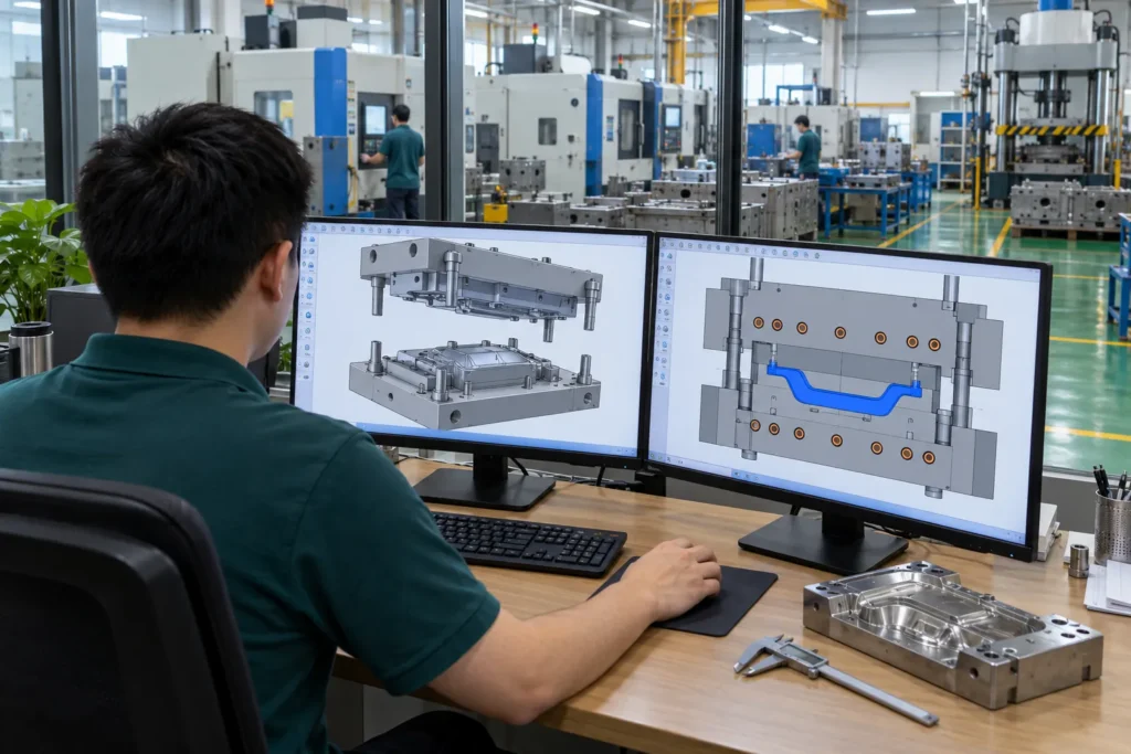
Many BMC and SMC defects can be designed out: flow lines, porosity, sink over ribs, warpage, blisters and cracks around bosses. Before mold design starts, our engineers check your 3D model against the chosen process and send a DFM report listing the changes we recommend.
Once you approve the DFM, we design the mold in 3D and send you the layout, heating, shear edge or gating, and ejection concept for review before steel is ordered.
What our DFM review covers
- Process choice: compression or injection, SMC or BMC
- Wall thickness and transitions
- Rib, boss and hole design
- Draft angles and textured surfaces
- Charge pattern or gate location, and flow length
- Inserts, holes and secondary machining
- Tolerances, flatness and warpage risk
Design guidelines for BMC and SMC parts (typical)
| Wall thickness | SMC: typically about 2–6 mm; BMC: typically about 1.5–5 mm; keep walls as uniform as possible |
|---|---|
| Ribs | Root thickness typically no more than about 0.75 of the adjoining wall, with root radii, to limit sink |
| Draft | Typically 1–3° per side; more for textured surfaces and deep walls |
| Radii | Avoid sharp internal corners; radii help flow and reduce cracking |
| Holes and bosses | Molded with core pins or machined after molding; core out thick bosses |
| Inserts | Metal inserts can be molded in; design them with knurls or undercuts for anchoring |
| Tolerances | Low shrinkage allows tight tolerances; agree critical dimensions at DFM |
DFM FAQ
Do you provide a DFM report before building the mold?
Yes. We review the part for the chosen process and send a DFM report with recommended changes before mold design starts.
Can a part designed for metal or thermoplastic be converted to BMC or SMC?
Often, yes. A conversion usually needs changes to wall thickness, ribs, draft and fastening features. We review the design and propose the changes.